As I mentioned previously, I wanted to free up some pins on the Pi Pico. I want to do this because I think I can support input from the trackpad on the same controller, and I’d like to implement RGB LEDs under the keyboard.
To free up the pins, there are two options that I’m considering:
- An IO Expander
- A couple of Shift registers
An IO expander is an integrated circuit that receives data and distributes it to its own pins, or conversely will pack up signals on its pins and send them to an attached microcontroller. The way that it differs from shift registers is that it has some smarts built into it. It typically has an I2C interface, but there are other options. Sometimes the have convenient features like built-in pull-up/down resistors that will prevent the pin from floating.
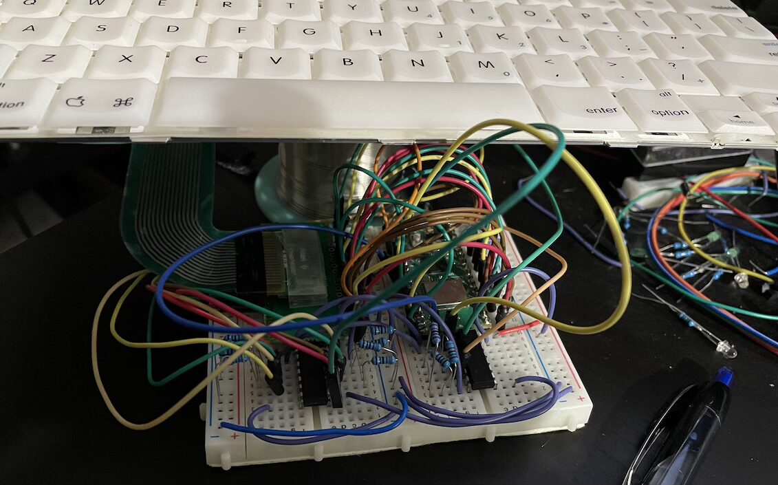
A shift register on the other hand is a relatively simple device. You trigger the register to ‘latch’ the values on the pins into its internal memory, and then you read it in one step at a time. Either solution is fine, and I happen to have a few shift registers on hand – so I’m going to use those.
Shift Registers
Many years ago, I built a Shift Register simulator in javascript. It was a serial-in, parallel-out register, based on the famous 74HC595. What we need for our purposes is the inverse register: Parallel-in, serial out. We want to get the state of all of the columns at a given moment, and give it to the microcontroller that will determine if any keys are pressed. There are several options, but a common choice is the 74HC165.
The new circuit looks like this:
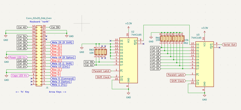
Note that only the columns go into the shift registers. The rows (and the meta keys) will still be handled directly by the microcontroller. This frees up 7 GPIO pins (after the 3 needed for the Shift register IO).
What’s next?
There are 26 pins on the FFC connector on the RPi500. I don’t yet know what those all are. There are 78 keys on the keyboard, which is easily covered by 8 rows and 10 columns (for instance), but it’s not clear from anything on the board what those pins go to. Tragically, unlike a lot of Raspberry Pi’s products, the RPi500 does not have an available schematic.
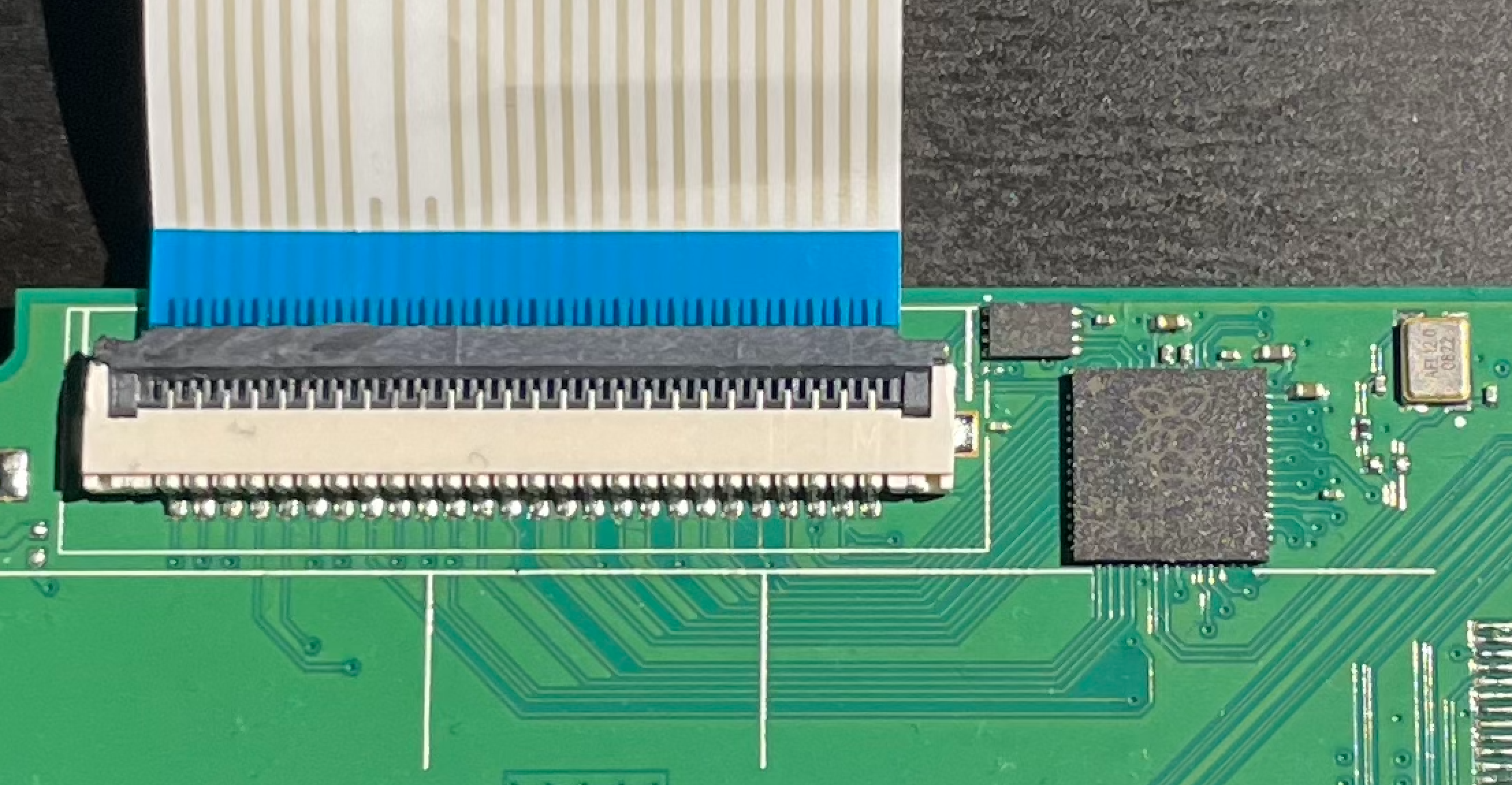
It’s not a dead-end though. One idea that comes to mind is to put Micropython on the chip, and turn on one GPIO at a time to map where they go. As I’ve said in the past, the worst case scenario is that I don’t use this chip for the keyboard and put my own $4 Pico in.
RGB
I’ve noted previously that I’d like to try to underlight the keys. I’ve seen one example of this and its pretty promising. Provided I can source power, I think I should be able to use very small RGB LEDs and put them up through punched-holes in the bottom of the keyboard.
Trackpad
It’d be ideal if I could handle the trackpad in the same device – KMK has mousekey support, and a couple of other folks have done some exploratory work on this front.